What is the Sage 200 Connector Tool?
The Sage 200 Connector Tool allows users to communicate directly with the Sage 200 application in order to both read data from your system as well as write data back to it.
In the current version of the tool we allow users to communicate with the core Financial and Commercial modules of Sage 200; Sales Ledger, Purchase Ledger, Nominal Ledger, Sales Order Processing, Purchase Order Processing and Stock Control.
So as an example, if the user has a commercial website selling goods to trade or retail customers, by using BPA Platform with the Sage 200 Professional Connector Tool it would be possible for the user to:
- Upload a full product catalogue to the website
- Upload product stock levels to the website
- Download new customers from the website to Sage 200
- Download new orders from the website for processing
Note that the above assumes that connectivity can be achieved with your website. This would normally be achieved through the BPA Platform web service connector tool, ftp or another specialist connector tool.
White Paper - Sage 200 Connector 5.1.3
Introduction
The Sage 200 Connector v5.1.3 Technical Overview introduces the Connector tool. The Sage 200 Connector provides connectivity between BPA Platform and a Sage 200 company database.
This Technical Overview introduces you to all available features of this release.
Sage 200 Connector Tool System Requirements
Sage 200 Professional and Sage Partner Cloud are supported, but not Sage Standard (there is a separate tool for this).
Sage 200 Versions fully supported are those within “current support” as determined by Sage’s lifecycle documentation.
End of Life Policy
We follow Sage’s own end of life policy for compatibility with older version of Sage 200. This effectively means:
- No new versions of the Requisitions module will be released for a Sage 200 version once that version enters “Extended Support”
- Once the Extended Support period has begun for a Sage 200 version then support for the Connector Tool will be on a best endeavours basis. If a solution cannot be found then it will be necessary for the user to upgrade to a supported version of Sage 200.
- At the conclusion of the Extended Support period no support will be given for the Connector Tool for the obsolete product.
For your reference the following article details the support dates for Sage 200.
On this page, the Lifecycle Document provides specific details on dates for extended support for each version.
Using This Guide
The main purpose of this guide is to provide you with information as to what data needs to be passed to the Sage 200 Tool. For example, if you were trying to post a customer, you would need to know that for the payment terms field you need to pass the database ID for the terms method that you wish to use rather than the name of the terms.
The guide is not intended as a guide to Sage 200 itself. It is assumed that, in using the BPA Platform Sage 200 Tool, the user has a working knowledge of Sage 200. For 3rd parties using the tool it is recommended that they work in close partnership with the client’s Sage 200 Business Partner.
In many instances within the guide you will be asked to provide data from a specific column from a particular table. The table may either have a limited set of pre-defined values (the SYSExchangeRateType table for example) or it may be a user value generated table (such as the analysis codes table). In either case, you can use the Select [field name] From [table name] within Microsoft SQL Server Management Studio to retrieve a list of the valid values.
Before attempting to use the tool you are advised to read the section entitled “Sample Tasks and Reference Information”.
Architecture
Figure 1 below provides a high-level system architecture diagram of the Sage 200 Connector Tool within the context of BPA Platform and the Sage 200 Application. The Sage 200 Connector Tool connects through the .Net assemblies of the Sage 200 Application, so respecting the business logic and security of the Sage 200.
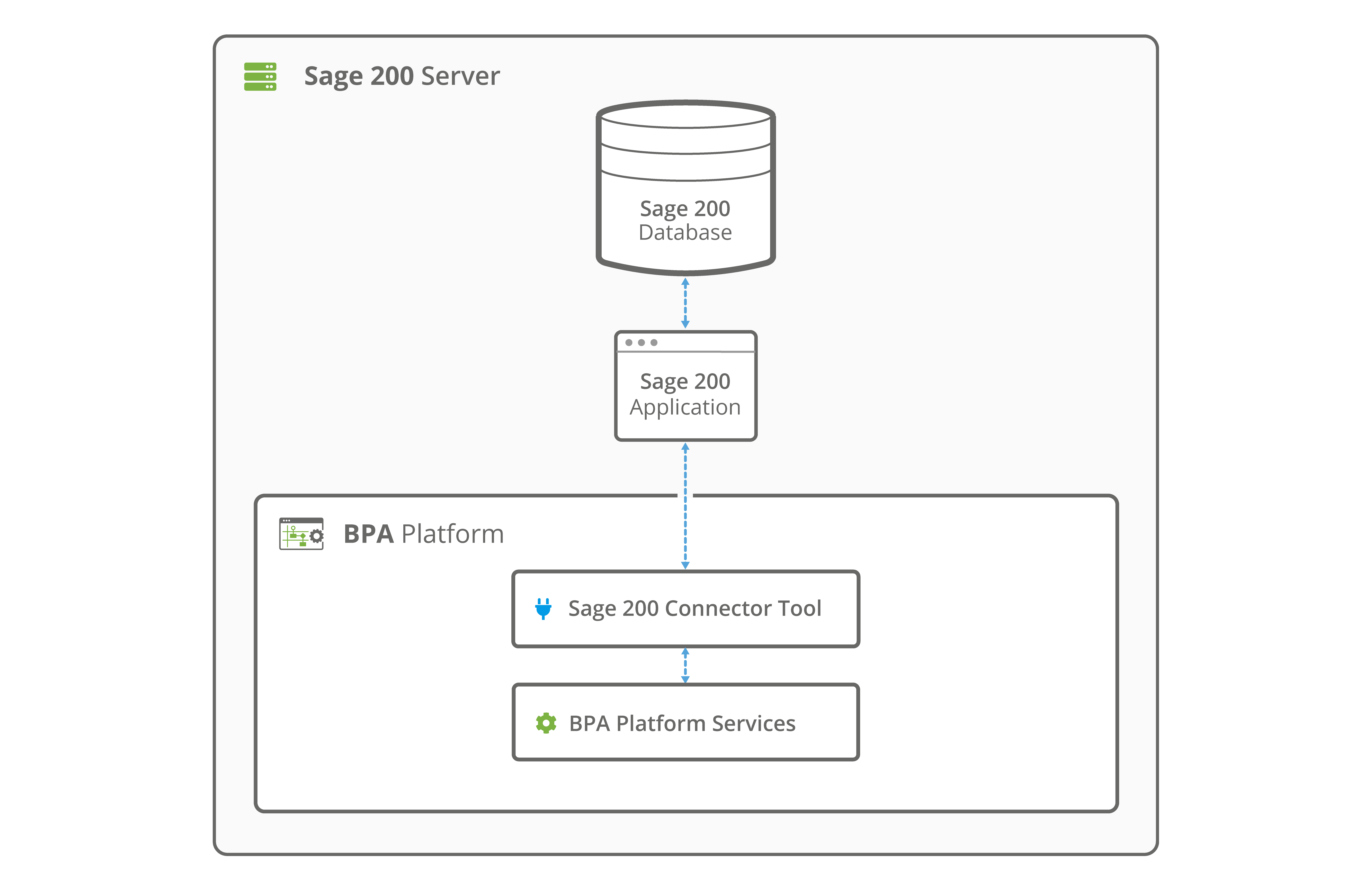
Figure 1 – System Architecture Diagram
The BPA Platform client, server and the Sage 200 Connector tool must all be installed on the machine hosting Sage 200.
The configuring of tasks using the connector tool through a BPA Platform Client, not connecting to the localhost server, requires both the Sage 200 Connector tool and the Sage 200 Client to be installed.
Sage 200 Connector Tool
Introduction
The Sage 200 Connector Tool is used to operate with data from/to a Sage 200 database. The operations available are Create, Delete, Get and Update.
The Tool transforms incoming XML data into an XML format for the specific Sage 200 object and operation selected. This XML is then passed to the Sage 200 API to interact with the data in the Sage 200 database. The response is exposed as XML from the Tool, which could include details of the object requested, errors from the provider, or the values of any automatically generated ID fields.
The Tool does not accept a BPA Platform recordset directly as input but BPA Platform variables containing XML data from any source at Task runtime may be utilised. In addition, a BPA Platform recordset can be processed by the Recordset to XML Tool first to transform it into XML if you have this Tool available.
Global Configuration
Once the Sage 200 Tool has been installed it will need configuring within BPA Platform.
To configure the tool open BPA Platform and browse to System, Tools, Specialist (Third Party). Upon opening the Specialist (Third Party) menu you will see the Sage 200 Connector Tool listed as a new item.
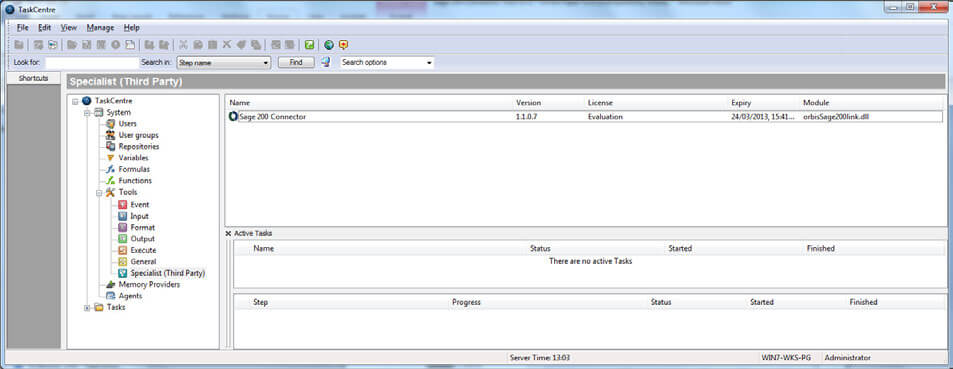
Figure 2 – Sage 200 Connector Global Configuration
Right click on the Tool and choose Properties.
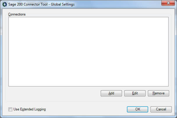
Figure 3 – Global Connection Configuration
The properties option allows you to add new connections to be used by the Sage 200 Tool. So choose Add to add a new connection.
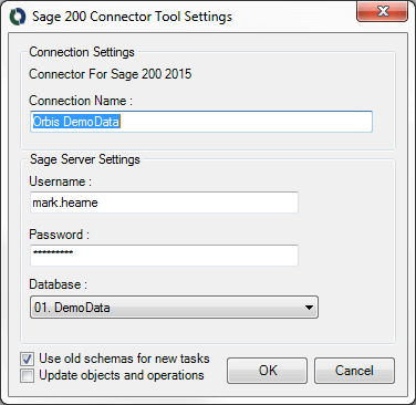
Figure 4 – Connection Configuration Dialog
The connection name should be descriptive, such that should you have more than one connection to Sage 200 (you would need a new connection for each Sage 200 database you want to connect to) it is clear which one is which.
- The username and password must be a valid Sage 200 username and password.
- The user must also have been given access to the required companies within the Sage 200 System
Administrator. - The user may be created as a Remote User.
- The database is the Sage 200 database into which you wish to post or retrieve data.
Global Configuration for Impersonated Users
Sage 200 is a click once app. This affects how the BPA Platform Connector Tool Fetches the Sage program files to run for impersonated users. Please make sure the following steps have been made before attempting to run the tool with the impersonated user (denoted as iUser):
- Through the sage 200 administration make sure the iUser is not restricted to a remote role.
- Log onto the BPA Platform Server Machine as the iUser and install the Sage200 Client app and log onto sage to ensure you generate the program data for the user.
- Connect to BPA Platform whilst logged onto the iUser and fill in the iUser logon information in the BPA Platform Connector Global Settings.
- You can then restrict the Sage200 role for the iUser to be a Remote/Web User.
Because of the Sage200 Product Structure you need permisions to the local files on the user you are impersonating, therefore try and be logged onto the user you are impersonating when you are changing the information stored.
Use Old Schemas for New Tasks (v4.0 onwards)
This setting determines what schema type, and hence what error xml type, new tasks will use when using the connection.
Using old schema types will place a Root node at the top of the schema tree as shown below when mapping fields within the tool:
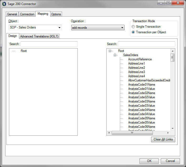
Tasks created using this methodology will utilise the old error output xml structure and as such will only be able to output a single error message irrespective of the number of errors that occur.
Using new schemas for new tasks will remove the Root node from the mapping screen as shown below:
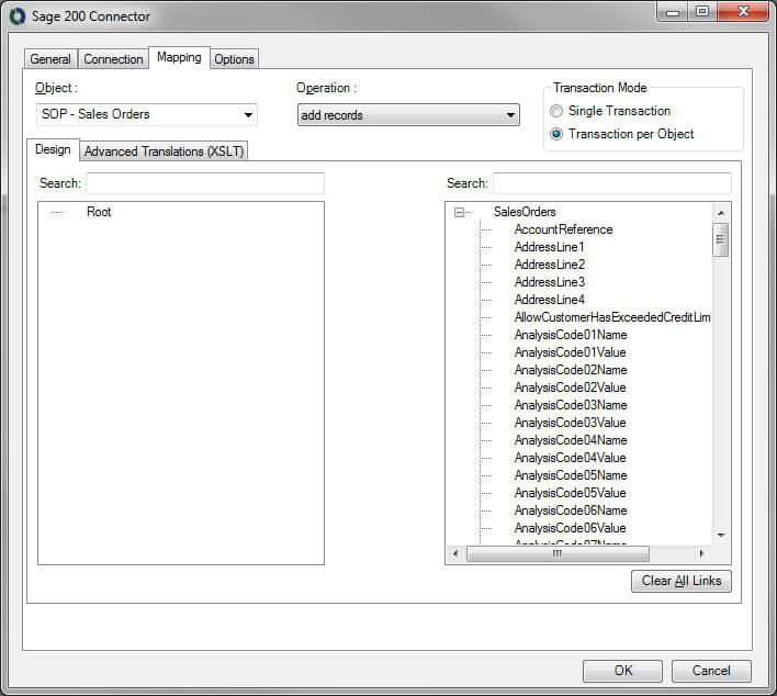
Tasks created using this methodology will be able to utilise the new error xml output and therefore receive multiple error messages from the system. An example of this would be sending 100 orders through in a single batch (Transaction Per Object mode) and 5 orders fail to process. The error xml would detail the error for all 5 of the failed orders rather than just the error from the first of the failed order.
Effect On Old Tasks
Any tasks created using old versions of the Sage 200 Connector Tool will effectively be using the old schema types. The setting against the connection configuration only applies to NEW tasks created using the connection. This ensures that all old tasks (with the Root Node) will continue to work following an upgrade from older versions of the Sage 200 Connector Tool to version 4.0 or higher.
If you wish to update an existing task to utilise the new error output mode then you would need to remove the Connector Tool step from the task and add it in again from scratch. It would then be necessary to update any steps after the Connector Tool step to utilise the new xml structure for the error output. Failure to do this will cause the task to error.
Step Configuration
General tab
At configuration time, when the Tool is added to a Task the Step will allow the user to select the data source which it will use at runtime through the General tab of the Sage 200 Connector dialog. See Figure 5 below.
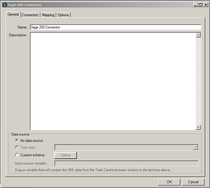
Figure 5 – Sage 200 Connector dialog – General tab
The data source can be either a Task Step, or a custom data source, including the use of BPA Platform variables.
If a Task Step is used, then the data source can be set to an available BPA Platform XML data source. Only those steps that are capable of natively exposing an XML document at runtime are listed (this may be another Sage 200 Connector Step or a Tool such as Recordset to XML).
It is also possible to define a custom data source. This data source has two parts – a definition of the schema used by the incoming data, and the selection of a BPA Platform variable that will contain the XML data at runtime.
Custom Schema Configuration
The Custom Schema Configuration dialog (Figure 5) is used to define the schema of the XML to be used as the input data source for the Sage 200 Connector Step. An XML schema defines the structure of the XML, in terms of what tags are present, and the nesting of the tags. The format used by the Sage 200 Connector Tool is the industry standard XSD format.
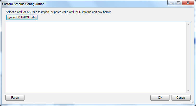
Figure 6 – Sage 200 Connector Custom Schema Configuration Dialog
If an XSD schema file is available for the XML that is to be used as the input data, then this can be loaded in from a file on disk (via the “Import XSD/XML File” button, which displays a file selection dialog) or pasted directly into the text box shown. Any XML passed into the step at runtime must conform to this schema. Otherwise an error will be reported.
Using an XSD schema file is the recommended way of defining the XML schema. However, if an XSD schema is not available, then an example of the XML that will be used at runtime can be loaded in or pasted into the text box.
Connection tab
Through the Connection tab of the Sage 200 Connector dialog, see Figure 7 below, a connection is selected from the list of connections previously created (set up in the Global Configuration for the Tool through the Connection Configuration dialog shown in Figure 2).
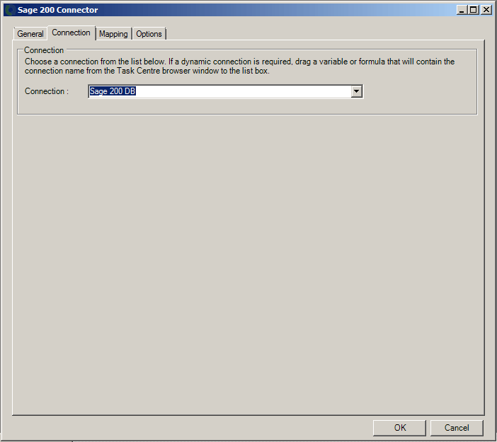
Figure 7 – Sage 200 Connector dialog – Connection tab
As an alternative to selecting a connection that has been previously created, a BPA Platform variable may be utilised by dragging and dropping it from the Task Browser dialog into the Connection field to create a dynamic connection. If the dynamic option is used, then at runtime the text in the variable should match the name of one of the connections set up in the Global Configuration and this connection is then used.
Mapping tab
Once the input data and the Sage 200 connection have been defined, the mapping of data from the source to a Sage 200 object, along with the operation required, is performed through the Mapping tab of the Sage 200 Connector dialog. See Figure 8 below.
The aim of this tab is to define the links between the incoming data and the outgoing data that is to be sent to the Sage 200 Connector Tool.
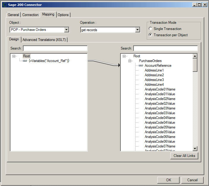
Figure 8 – Sage 200 Connector dialog – Mapping tab
The Object dropdown holds a list of objects available for the selected Sage 200 connection. Selecting an object will change the tree display in the right hand pane to reflect the fields and child objects available for that selected object.
The objects and operations available are shown in the tables below. Objects in bold are new for this version whilst
those in italics have been amended for this version.
| Object | Operation |
|---|---|
| SL – Customer Records | Get Records, Delete Records, Update Records and Add Records |
| SL – Customer Records Simple | Add Records, Update Records |
| SL – Customer Transactions | Add Records, Update Records and Get Records |
| SL – Customer Transaction Memos | Add Records, Update Records, Get Records and Delete Records |
| SL – Customer References | Get Records |
| SL – Customer Account Memos | Add Records, Update Records, Get Records and Delete Records |
| SL – Customer Aged Balances | Get Records |
| SL – Customer Allocations | Add Records and Get Records |
| SL – Customer Account Statuses^ | Update Records and Get Records |
| PL – Supplier Records | Add Records, Update Records, Get Records and Delete Records |
| PL – Supplier Records Simple | Add Records, Update Records |
| PL – Supplier Transactions | Add Records, Update Records and Get Records |
| PL – Supplier Transactions Memos | Add Records, Update Records, Get Records and Delete Records |
| PL – Supplier References | Get Records |
| PL – Factor Houses | Add Records, Update Records, Get Records and Delete Records |
| PL – Supplier Account Memos | Add Records, Update Records, Get Records and Delete Records |
| PL – Payment Groups | Update Records and Update Records |
| PL – Supplier Aged Balances | Get Records |
| PL – Authorise Invoices | Update Invoices |
| PL – Supplier Allocations | Add Records, Get Records |
| PL – Supplier Account Statuses^ | Update Records and Get Records |
| NL – Nominal Codes | Add Records, Update Records, Get Records and Delete Records |
| NL – Cost Centres | Add Records, Update Records, Get Records and Delete Records |
| NL – Departments | Add Records, Update Records, Get Records and Delete Records |
| NL – Report Categories | Add Records, Update Records, Get Records and Delete Records |
| NL – Nominal Journals | Add Records |
| NL – Nominal Account Memos | Add Records, Update Records, Get Records and Delete Records |
| NL – Nominal Budgets | Get Records and Update Records |
| NL – Fixed Assets | Add Records, Update Records, Get Records and Delete Records |
| CB – Bank Accounts | Add Records, Update Records, Get Records and Delete Records |
| CB – Opening Balances | Add Records |
| CB – Bank Account Memos | Add Records, Update Records, Get Records and Delete Records |
| CB – Nominal Transactions | Add Records |
| PB – Price Bands | Add Records, Update Records, Get Records and Delete Records |
| PB – Stock Item Prices | Update Records, Get Records |
| PB – Customer Discount Groups | Add Records, Update Records, Get Records and Delete Records |
| PB – Product Group Discounts | Add Records, Update Records, Get Records and Delete Records |
| PB – Stock Item Discounts | Add Records, Update Records, Get Records and Delete Records |
| SOP – Sales Orders | Add Records, Update Records and Get Records |
| SOP – Sales Returns | Add Records, Update Records and Get Records |
| SOP – Sales Quotations | Add Records and Get Records |
| SOP – Sales Templates | Add Records and Get Records |
| SOP – Sales Proformas | Add Records and Get Records |
| SOP – Customer Delivery | Addresses Add Records, Update Records, Get Records and Delete Records |
| SOP – Payment Methods | Add Records, Update Records, Get Records and Delete Records |
| SOP – Additional Charges | Add Records, Update Records, Get Records and Delete Records |
| SOP – Order Despatches | Add Records |
| SOP – Order Receipts | Add Records |
| SOP – Print Invoices | Add Records |
| SOP – Print Credit Notes | Add Records |
| SOP – Print Order Acknowledgements | Add Records |
| SOP – Print Picking List | Add Records |
| SOP – Cancel SOP Orders | Add Records |
| SOP – Cancel SOP Returns | Add Records |
| SOP – Sales Order Items | Add Records, Update Records, Get Records and Delete Records |
| SOP – Post SOP Orders | Add Records |
| SOP – Traceable Allocations | Get Records |
| SOP – Allocate Orders | Add Records |
| SOP – Archive SOP Order Returns | Add Records |
| POP – Purchase Orders | Add Records, Update Records and Get Records |
| POP – Purchase Returns | Add Records, Update Records and Get Records |
| POP – Goods Received | Add Records |
| POP – Goods Despatched | Add Records |
| POP – Additional Charges | Add Records, Update Records, Get Records and Delete Records |
| POP – Record POP Invoices | Add Records |
| POP – Cancel POP Orders | Add Records |
| POP – Cancel POP Returns | Add Records |
| POP – Archive POP Order Returns | Add Records |
| POP – Print Purchase Orders | Add Records |
| INV – Credit Notes | Add Records, Update Records and Get Records |
| INV – Invoices | Add Records, Update Records and Get Records |
| INV – Print Credit Notes | Add Records |
| INV – Print Invoices | Add Records |
| STK – Stock Items | Add Records, Update Records, Get Records and Delete Records |
| STK – Add Stock | Add Records |
| STK – Customer Allocations | Add Records |
| STK – FOC Customer Issues | Add Records |
| STK – Internal Issues | Add Records |
| STK – Project Issues | Add Records |
| STK – Stock References | Add Records |
| STK – Write Off | Add Records |
| STK – Internal Allocations | Add Records |
| STK – Internal Areas | Add Records, Update Records, Get Records and Delete Records |
| STK – Write Off Categories | Add Records, Update Records, Get Records and Delete Records |
| STK – Warehouses | Add Records, Update Records, Get Records and Delete Records |
| STK – Units | Add Records, Update Records, Get Records and Delete Records |
| STK – Stock Item Memos | Add Records, Update Records, Get Records and Delete Records |
| STK – Stock Balances | Get Records |
| STK – Stock Transfers | Add Records |
| STK – Traceable Items | Get Records |
| PA – Archive Projects | Add Records |
| PA – Charge Rate Types | Add Records, Update Records, Get Records and Delete Records |
| PA – Cost Adjustments | Add Records |
| PA – Cost Rate Types | Add Records, Update Records, Get Records and Delete Records |
| PA – Project Bills | Add Records and Get Records |
| PA – Project Item Statuses | Update Records, Get Records |
| PA – Project Statuses | Add Records, Update Records, Get Records and Delete Records |
| PA – Project Units of Measure | Add Records, Update Records, Get Records and Delete Records |
| PA – Projects Cost Opening Balances | Add Records |
| PA – Projects From Templates | Add Records |
| PA – Projects Item Analysis Values | Update Records |
| PA – Projects Item Billing Customers | Update Records |
| PA – Projects Revenue Opening Balances | Add Records |
| PA – Resurrect Projects | Add Records |
| PA – Revenue Adjustments | Add Records |
| PA – Timesheets | Add Records, Update Records, Get Records and Delete Records |
| SYS – Tax Rates | Add Records, Update Records and Get Records |
| SYS – Country Codes | Add Records, Update Records, Get Records and Delete Records |
| SYS – Credit Bureaus | Add Records, Update Records, Get Records and Delete Records |
| SYS – Credit Positions A | dd Records, Update Records, Get Records and Delete Records |
| SYS – Transaction Analysis Codes | Add Records, Update Records, Get Records and Delete Records |
| SYS – Trader Contact Roles | Add Records, Update Records, Get Records and Delete Records |
| SYS – Analysis Codes | Add Records, Update Records, Get Records and Delete Records |
| SYS – Analysis Code Values | Delete Records |
| SYS – Currencies | Add Records, Update Records and Get Records |
| SYS – Accounting Periods | Get Records |
| SYS – Disconnected Logins | Get Records and Delete Records |
| BOM – BOM Records | Add Records, Update Records, Get Records and Delete Records |
| BOM – BOM Record Statuses | Update Records |
| BOM – Record Built Items | Add Records |
^SL – Customer Account Statuses and PL – Supplier Account Statuses are only applicable to Sage 200 2017 onwards. This functionality does not exist in earlier versions of Sage 200.
The Operation dropdown displays the operations that the selected object supports.
The aim of this screen is to define the links between the incoming XML data and the outgoing XML data that is to be sent to the Web Service and then into Sage 200.
These links are created by dragging and dropping fields from the left hand XML tree control to the right hand XML tree control.
BPA Platform variables and formulas can be included in the source data, by simply dragging them from the BPA Platform Browser dialog into a branch node in the input XML tree control. Once in place, these can then be linked to the output XML tree control in the same way as normal fields are.
Creating the links in the user interface defines how, at runtime, the incoming XML is to be translated into the XML required for the given object and operation.
The method used to translate the XML is XSLT (eXtensible Stylesheet Language Transformations), which is an industry standard mechanism for performing XML translations. There is an Advanced Translation (XSLT) tab on the control, which will show the XSLT currently being generated for the given set of links created. In the case of the user interface not being able to handle a particularly quirky requirement for transforming data, it is possible for the user to go into ‘Enable Free Type Mode’ by checking this option, where XSLT can be input directly to achieve a transformation from the source XML format into the XML format required for the desired object and operation. XSLT knowledge will be needed to do this.
Filter Links
For the query operations, the user interface allows the user to designate fields within the destination object to use as the filter when performing the operation. Such fields are linked in the normal way from the source data, but are then marked as a “Filter Link”.
This means that at runtime, the Tool will compare the value in the source data against the Sage 200 database (the condition for the comparison can be set in the UI, and can be “=”, “<” or “>”) when performing the operation. The presence of multiple filter links implies that all conditions must be met on all comparisons.
Rollback Functionality
When using the Sage 200 Tool there are always two options available to you when using the Add or Update operations; Single Transaction and Transaction per Object.
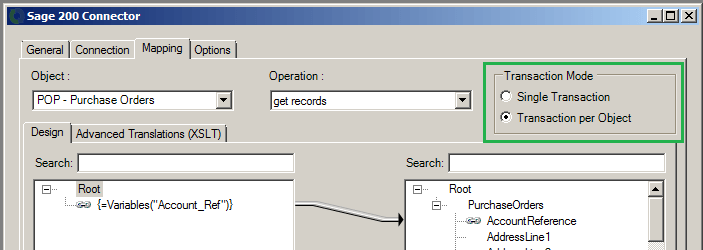
Which one of these two options you choose when creating tasks is very important as it affects how transactions are rolled back should there be a problem.
Single Transaction
This option effectively means that all postings must complete before the task can progress to completion. So if you were passing 50 sales orders to the Sales Order object (using the Add operation) and one of the sales orders had an invalid customer account, then none of the sales orders would post. All 50 would need to be valid orders in order for the posting to occur.
Transaction per Object
Conversely, using the same example from above, the ‘transaction per object’ mode would allow 49 of the 50 transactions to be posted with the one remaining transaction reporting an error in the error log.
Most of our sample tasks use the Transaction per Object mode although this is just a personal preference – you should decide for yourself which mode suits your required functionality best.
If using the ‘transaction per object’ mode it is highly recommended that you set the tool to use the Options as shown below – so allow the task to Continue if an error occurs.
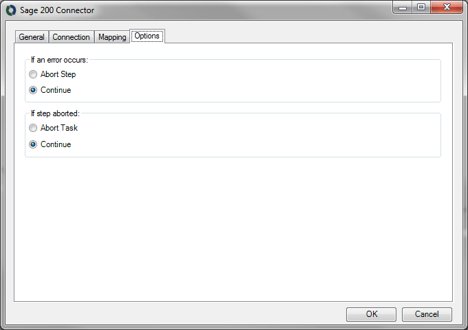
The reason for this is simple – if 49 of the sales orders post and 1 fails then you would want the task to continue onto other steps to allow for any potential write back of posted IDs etc.
If the step is set to abort then your source data would have no knowledge of the 49 orders that posted and is likely to attempt to post them a second time.
Tool Output
The Tool may output two separate XML documents depending on the Transaction Mode selected in the Mapping tab. The contents for each document type are described below.
If the Transactions per Object mode is selected then potentially both a ‘success’ and an ‘error’ XML document will be produced; each containing the successful or error objects respectively.
If the Single Transaction mode is selected then either a ‘success’ or ‘error’ XML document will be produced. An ‘error’ XML document is always produced if an error is returned by the API.
‘success’ XML document
This document will contain the following:
- The input data mapped for the object
- Data returned from Sage 200, in the case of a Get method
- The key fields for the entity instances affected by the method. For example, in the case of a ‘Create’, the key fields for the top level object instances created would be returned.
‘error’ XML document
There are two potential error xml documents that you can receive depending on the setup of your connection.
Using Old Schema Types
This document will contain the following:
- Any error that occurs is created as an
<ERROR>node. <Object>– The name of the requested object (e.g.PurchaseOrders)<CODE>– Always the word Error.<MESSAGE>– The error message returned by Sage.<EXTENDEDINFO>– The external ID of the data passed to the object.<INPUTDATA>– Blank
The sub-nodes of the ERROR node are:
Each XML document output by the Tool can then be used within other BPA Platform Tools, either as is or through conversion to a BPA Platform recordset using the XML to Recordset Tool.
Note that the error output will only contain the first error that the tool encounters. So if you attempt to create 10 sales orders and each one errors, only the first error for the first sales order will be returned within the error xml.
As an alternative to the error xml returned by the tool there is also an ExtendedErrorXmlString available as a property of the tool. This is available via the Browser against the Sage 200 Connector Tool and contains the first error from each record passed to the tool. So if you were passing the same 10 orders to the tool as above then the ExtendedErrorXmlString would contain the first error encountered for each of the 10 orders.
Using New Schema Types
This document will contain the following:
- Any error that occurs is created as an
<ERROR>node. <Object>– The name of the requested object (e.g.PurchaseOrders)<CODE>– Will be either Error or Rollback. See below for further info.<MESSAGE>– The error message returned by Sage.<EXTENDEDINFO>– The external ID of the data passed to the object.<INPUTDATA>– The header node from the input data. So if you were creating a purchase order then the inputdata node would contain all of the fields and data from the order header passed to the object.
The sub-nodes of the ERROR node are:
Each XML document output by the Tool can then be used within other BPA Platform Tools, either as is or through conversion to a BPA Platform recordset using the XML to Recordset Tool.
Note that the error output will contain an error message for each error record that the tool encounters. So if you attempt to create 10 sales orders and each one errors, 10 full error messages will be returned within the error xml, one for each order. Note that only one error message will be returned per order, so if the customer did not exist AND the currency was invalid then only one of these errors will be returned.
If you utilise the Single Transaction mode when setting up a task then you may also see a “Rollback” Error Code. So if you passed 10 sales orders to the object but only one sales order errored, then all 10 orders would be included in the error response with one reporting an Error Code of “Error” but the other nine showing an error code of “Rollback”. This means that you are still informed that all 10 have failed to process to Sage 200 but for different reasons.
Runtime
The incoming XML is translated into the XML format for the object and operation selected in the configuration. The data for the linked fields is brought across into the output XML – only those fields that were linked are brought across. This data is passed to the Sage 200 .Net Assemblies which then process the data, performing the operation requested, responding with a success or error message which is converted into an XML document containing the response. The XML can then be used by other BPA Platform Steps.
Error Handling
It is of course possible that errors may happen when the Tool is processing data. These errors could come from a variety of sources and for a variety of reasons, including:
- User privilege errors
- Errors from the Sage 200 API (see Tool Output above)
- Warnings/Messages from the Sage 200 API (see Tool Output above)
All other error types are written directly to the BPA Platform event log.