- What is the Sage 1000 Connector Tool?
- White Paper - Sage ERP 1000 (Line 500) Connector 3.0
- Sage 1000 Integration Architecture
- Global Configuration
- Step Configuration
- Working with Other Tools
- Supported Objects
- Tool Output
- About the Sage 1000 Connector Web Service
- Runtime
- Error Handling
- Sage 1000 Accounts Security
What is the Sage 1000 Connector Tool?
The Sage 1000 (Line 500) Connector Tool Pack provides a simple, straightforward way of enabling connectivity between BPA Platform and Sage ERP 1000 (Line 500). Through the easy to use interface this allows you to connect with one or more companies to automate the retrieval and input of items such as purchase orders, sales orders, customers or stock. The Sage 1000 connector tool has the advantage of writing data through the Sage API which uses business rules defined by Sage for validation, ensuring only expected and accurate data is inserted at all times.
The Sage 1000 Connector tool uses XML as its input and output data format. Interoperation with standard BPA Platform tools is achieved by the use of the BPA Platform XML tools which allow conversion of standard BPA Platform recordsets to and from XML.
Handling of events within Sage ERP 1000 (Line 500) can be achieved by use of a standard BPA Platform trigger event on the Sage ERP 1000 (Line 500) database tables.
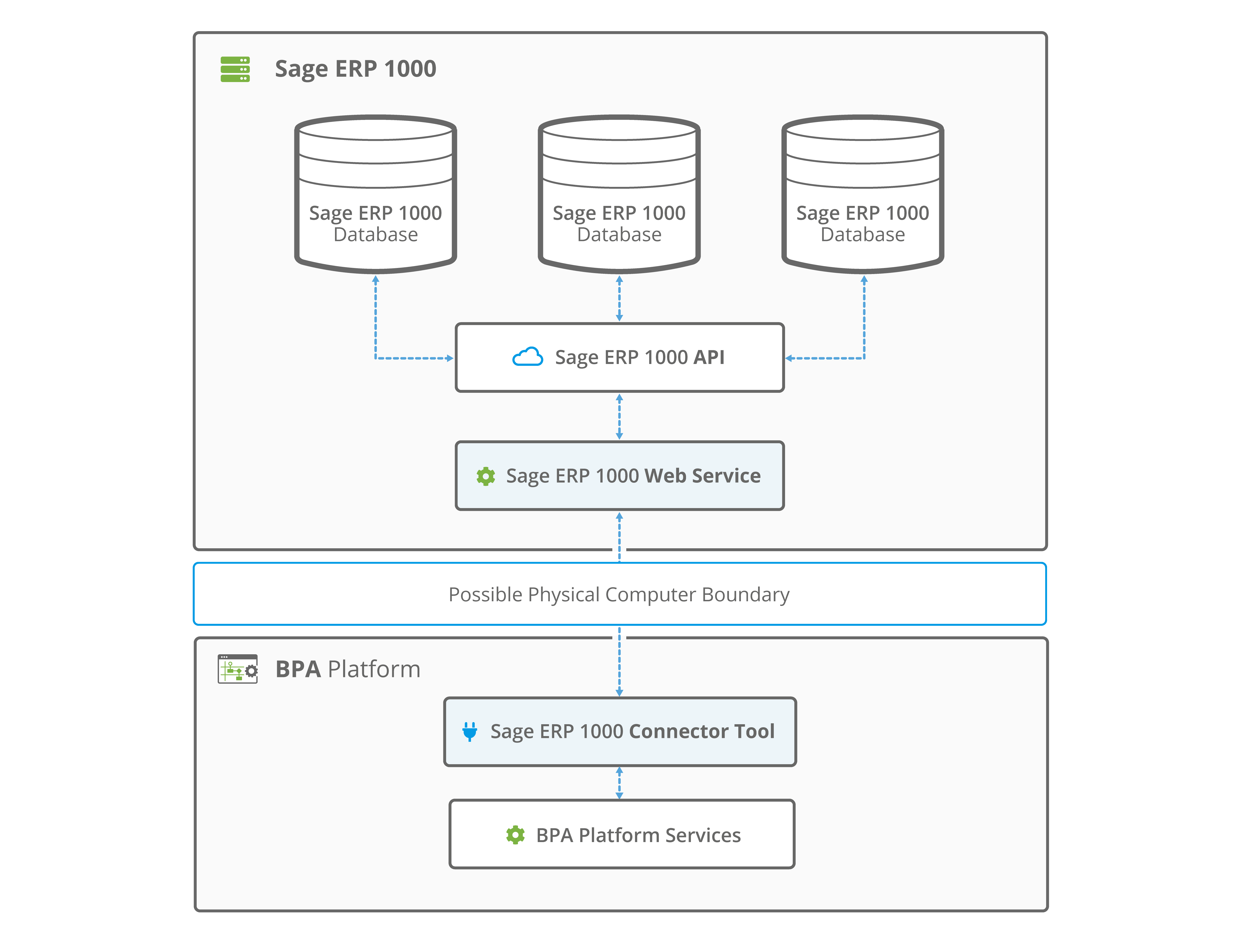
The Sage ERP 1000 integration tool itself does not directly connect to Sage ERP 1000 (Line 500). Instead, all data transfer to and from Sage ERP 1000 (Line 500) is done via the Sage 1000 API, and this takes place in a web service that is distributed with the tool. This allows distribution of the components so that the BPA Platform server does not have to be on the same machine as the Sage 1000 API.
When combined with other tools of BPA Platform, the Sage 1000 Connector provides an enhanced method for delivering data to and from your Sage ERP 1000 (Line 500) application. Company databases can be managed with a decreased level of manual input, ensuring the error of human nature is removed and consistent, accurate information is entered at all times.
The Sage Line 500 integration tool serves as a mechanism to enable a variety of automated interactions; some examples include:
- The automatic creation of purchase orders, sales orders, customers and stock.
- The scheduled retrieval of company data, i.e. sales orders, for monthly report generation.
- The synchronisation of one or more companies. For example, a change made to customer shipping details in one company is automatically reflected in another.
- The synchronisation of your Sage ERP platform with an online web shop as part of a larger integration solution for order fulfilment.
White Paper - Sage ERP 1000 (Line 500) Connector 3.0
The Sage ERP 1000 (Line 500) white paper describes how to use the tool.
System Requirements
The Sage 1000 Connector tool pack requires BPA Platform (formerly known as TaskCentre) 4.6 SR1a and above.
It is compatible with the following versions of Sage Line 500 and Sage ERP 1000:
- Sage Line 500 version 6
- Sage Line 500 version 7
- Sage Line 500 version 7.1
- Sage ERP 1000 version 2.3
- Sage ERP 1000 version 3
- Sage ERP 1000 version 4
For more in depth details relating to the requirements, please contact our Support department.
Sage 1000 Integration Architecture
The diagram below provides a high-level system architecture diagram of the Sage 1000 Connector tool within the context of BPA Platform and Sage ERP 1000 (Line 500).
Items highlighted in blue are part of the Sage 1000 Connector Tool Pack.
Global Configuration
The global configuration for this tool is used to create a connection to a Sage ERP 1000 (Line 500) company database. Multiple connections can be created, one for each company.
The tool communicates with the web service on the Sage Server machine to retrieve a schema of all available objects and operations. When the connection is selected at task level, the company objects and object fields are exposed allowing BPA Platform data to be mapped for sending at runtime.
The global configuration can be accessed via the toolbar: Manage > Tools > Data Connectors > Sage 1000 (Line 500) Connector. Or, via the BPA Platformsystem tree within the Data Connectors node.
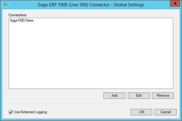
Click Add to create a new connection to Sage ERP 1000 (Line 500).
Connection Configuration
Within the Connection Configuration you must supply a name for the connection along with the location of the Sage Server machine and the credentials of a Sage API user:
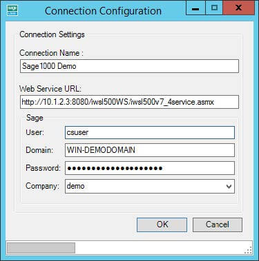
- The Connection Name supplied is used for identification purposes and is how it will be displayed when presented for selection within a task. The name is alphanumeric only and supports the use of 30
characters. - The Web Service URL is the location of the Sage Server where the BPA Platform Sage ERP 1000 (Line
500) Web Service has been installed. On the Sage Server machine this can be obtained from IIS by browsing oniwsl500WSunder the website where the web service resides. From the directory select the optioniwsl500v7_4Service(version dependant) to display the URL required by the connection. This will be in the form of, for example:http://localhost:8080/iwsl500WS/iwsl500v7_4Service.asmx- If BPA Platform is remote, an IP address or machine name of the Sage Server can be supplied in place of
localhost. A port number must be present in the URL otherwise the connection will fail.
- You must provide the Sage details for the Sage 1000 Connector to use:
- The User field requires the name of a Windows user that has been mapped to a Sage ERP 1000 (Line 500) user, permitting interactions with Sage via the API. This Windows account is usually created locally during the initial install of the Sage Server and by default is known as
csuser. This can be verified via the Sage API configuration tool. - The Domain field requires the domain that the Windows account exists in.
- The Password is the password of the same Windows user account.
- The Company drop down list will reveal the available Sage 1000 companies once all details have been correctly supplied.
- The User field requires the name of a Windows user that has been mapped to a Sage ERP 1000 (Line 500) user, permitting interactions with Sage via the API. This Windows account is usually created locally during the initial install of the Sage Server and by default is known as
Use Extended Logging
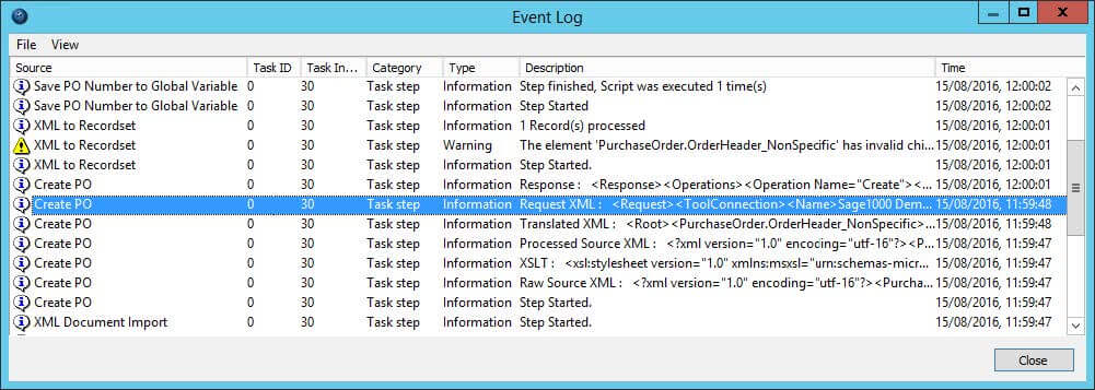
Ticking the option Use Extended Logging will enable the request and response XML of each web service call to be viewed in the BPA Platform event logs. Turning the option on will enable extended logging for all connections listed in the global configuration.
This can be beneficial for troubleshooting purposes, being able to see what is being sent by a task at runtime can help identify any anomalies that may prevent a web call from succeeding.
The event log for a task will start showing request and response content from the time the task next runs and will continue to do so until extended logging is disabled.
Example Extended Log Output
Step Configuration
About the General Tab
The General tab allows the step to be named and described. An XML data source may also be selected for the tool to consume. This will expose the XML schema within the tool and allow it to be mapped to objects of a Sage ERP 1000 (Line 500) company.
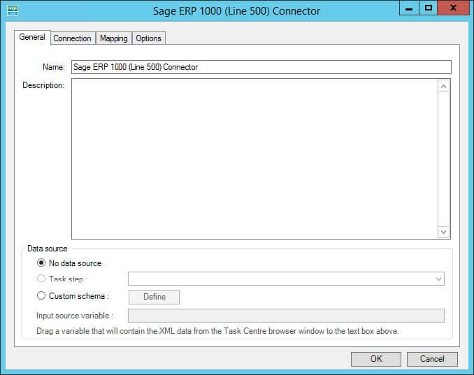
The Data source can be either be an existing task step, or a custom source allowing the use of a task variable.
The Task Step drop down list allows you to select an available step in the task that is capable of natively exposing an XML document. For example, a Convert Recordset to XML step or even another Sage 1000 Connector step. Selecting this option will consume the output XML of the step and will automatically determine the schema (XSD). The schema will then be presented within the Mapping tab for the XML data to be mapped to the fields of an object.
Selecting Custom Schema allows the use of a task variable containing XML as its value. The variable is dragged from the task browser and placed in the Input Source Variable field. The schema describing the structure of the XML in the variable must then be supplied using the Define button.
Custom Schema Configuration
The Custom Schema Configuration dialog box is used to define the schema of the XML stored by a variable.
An XML schema defines the structure of the XML, in terms of what tags are present and the nesting of the tags. The format used by the Sage 1000 Connector tool is the industry standard XSD format.
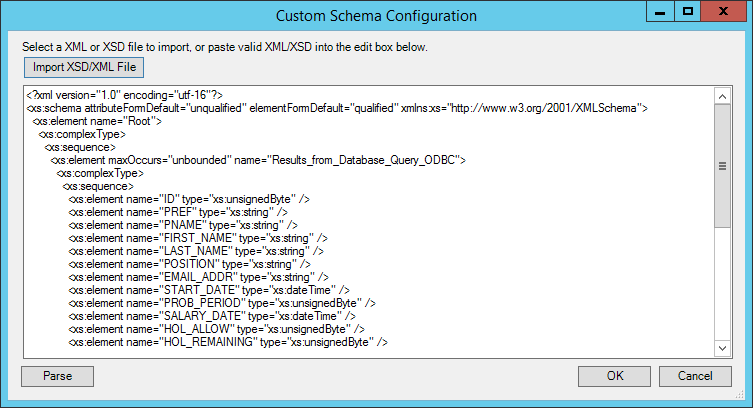
If an XSD schema file is available for the XML that is to be used as the input data, then this can be loaded in from a file on disk (via the Import XSD/XML File button) or copied directly into the text box shown. Any XML passed into the step at runtime must conform to this schema otherwise an error will be reported.
Using an XSD schema file is the recommended way of defining the XML schema. However, if an XSD schema is not available, then an example of the XML that will be used at runtime can be loaded in or copied into the text box. If an XML document is used, then the schema can be determined by pressing the Parse button.
About the Connection Tab
The Connection tab is used to select a connection to a Sage ERP 1000 (Line 500) company which will expose the available objects for mapping within the Mapping tab.
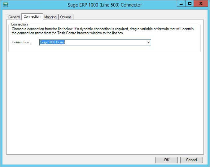
The drop down list displays all available connections previously created in the tool global configuration.
As an alternative to selecting a connection that has been previously created, a BPA Platform variable may be utilised by dragging and dropping it from the task browser into the Connection field to create a dynamic connection.
If the dynamic option is used, then at runtime the text in the variable should match the name of one of the connections set up in the Global Configuration.
About the Mapping Tab
The Mapping tab is used to define links between the incoming data and the outgoing data that is to be sent to Sage ERP 1000 (Line 500) via the API. Once a connection has been specified the objects and operations available will be exposed for selection.
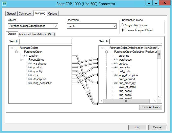
An object is first selected followed by the operation required. The XML structure of the incoming data source is displayed in the left-hand pane whilst the Sage ERP 1000 (Line 500) object data is displayed in the right.
A mapping is completed by dragging a field from the data source left XML tree to a field on the tool output right XML tree, a visual link of the mapping will then be displayed in the middle.
The Object drop-down holds a list of objects available for the selected Sage ERP 1000 (Line 500) connection. Selecting an object will change the tree display in the right hand pane to reflect the fields and child objects available for that selected object.
The Operation drop-down displays the operations that the selected object supports. These are Create, Update, Query, and Delete, and any special methods available for the selected object.
BPA Platform variables and formulas can be included in the source data, by simply dragging them from the task browser into a branch node in the input XML tree control. Once in place, these can then be linked to the output XML tree control in the same way as normal fields.
Creating the links in the user interface defines how, at runtime, the incoming XML is to be translated into the XML required for the given object and operation.
The method used to translate the XML is XSLT (eXtensible Stylesheet Language Transformations), which is the industry standard mechanism for performing XML translations. There is an Advanced Translation (XSLT) tab on the control, which will show the XSLT currently being generated for the given set of links created.
In the case of the user interface not being able to handle a particularly quirky requirement for transforming data, it is possible for the user to go into Enable Free Type Mode by checking this option, where XSLT can be input directly to achieve a transformation from the source XML format into the XML format required for the desired object and operation. XSLT knowledge will be needed to do this.
Filter Links
For the query operations, the user interface allows the user to designate fields within the destination object to use as the filter when performing the operation. Such fields are linked in the normal way from the source data, but are then marked as a “Filter Link”. This means that at runtime, the tool will compare the value in the source data against the Sage ERP 1000 (Line 500) database (the condition for the comparison can be set in the UI and can be =, <, >, or !=) when performing the operation. The presence of multiple filter links implies that all conditions must be met on all comparisons.
Working with Other Tools
Below is a list of other steps that a Sage 1000 Connector tool can directly interact with to consume information from.
Consuming from Other Tools
| Icon | Tool Name | Tool Category |
|---|---|---|
| Import Flat File | Input | |
| Import XML Document | Input | |
| Convert Recordset to XML | Format | |
| Web Service Connector | Data Connectors | |
| Sage 1000 (Line 500) Connector | Data Connectors |
Exposing to Other Tools
A Sage 1000 (Line 500) Connector step can also directly expose its output for use by the following steps listed below.
| Icon | Tool Name | Tool Category |
|---|---|---|
| Convert XML to Recordset | Format | |
| Run Microsoft Reporting Services | Format | |
| Save File | Output | |
| Web Service Connector | Data Connectors | |
| Sage 1000 (Line 500) Connector | Data Connectors |
Supported Objects
The objects and operations currently available are shown in the table below:
Operation Legend
C — Create | Q — Query | D — Delete | U — Update |
P — Post | DE — Despatch | DNP — DespatchNotePrint | GP — GetPrices |
CC — CreditCustomer | IC — Invoice Customer | CTO — ConvertTo Order |
Version 6 Objects
| Object | Child Object | Operation | Line 500 | Sage 1000 | |||
|---|---|---|---|---|---|---|---|
| 6 | 7 | 2.3 | 3.0 | 4.0 | |||
| AccountsPayable.InvoiceHeader | InvoiceLine | C Q D U | |||||
| AccountsPayable.InvoiceLine | C Q D U | ||||||
| AccountsPayable.Supplier | C Q D U | ||||||
| AccountsReceivable.Bank | Q | ||||||
| AccountsReceivable.CashHeader | CashLine | C Q D U P | |||||
| AccountsReceivable.CashLine | C Q D U | ||||||
| AccountsReceivable.Customer | C Q D U | ||||||
| AccountsReceivable.InvoiceHeader | InvoiceLine | C Q D U | |||||
| AccountsReceivable.InvoiceLine | C Q D U | ||||||
| AccountsReceivable.RefundHeader | RefundLine | C Q D U P | |||||
| AccountsReceivable.RefundLine | C Q D U | ||||||
| AccountsReceivable.Transaction | Q | ||||||
| CompanySetup.VatCode | Q | ||||||
| GeneralLedger.JournalHeader Recurring | JournalLine | Q | |||||
| Object | Child Object | Operation | Line 500 | Sage 1000 | |||
|---|---|---|---|---|---|---|---|
| 6 | 7 | 2.3 | 3.0 | 4.0 | |||
| GeneralLedger.JournalHeader Reversing | JournalLine | Q | |||||
| GeneralLedger.JournalHeader Normal | JournalLine | Q | |||||
| GeneralLedger.JournalHeader Standard | JournalLine | Q | |||||
| GeneralLedger.JournalLine | C Q D U | ||||||
| InventoryControl.BatchQueue | Q | ||||||
| InventoryControl.Stock | C Q D U GP | ||||||
| InventoryControl.Warehouse | Q | ||||||
| PurchaseOrder.CreditNoteHeader | CreditNoteLine | C Q D U | |||||
| PurchaseOrder.CreditNoteLine | C Q D U | ||||||
| PurchaseOrder.InvoiceHeader | InvoiceLine | C Q D U | |||||
| PurchaseOrder.InvoiceLine | C Q D U | ||||||
| PurchaseOrder.OrderHeader | [OrderLine], ProductLine, ServiceLine, CommentLine | C Q(v6) DU | |||||
| PurchaseOrder.OrderLine ProductLine | C Q(v6) DU | ||||||
| PurchaseOrder.OrderLine ServiceLine | C Q(v6) DU | ||||||
| PurchaseOrder.OrderLine CommentLine | C Q(v6) DU | ||||||
| PurchaseOrder.Service | Q | ||||||
| SalesOrder.CreditNoteHeader | [CreditNoteLine], ProductLine, ServiceLine, CommentLine | C Q D U CC | |||||
| SalesOrder.CreditNoteLine ProductLineLine | C Q D U | ||||||
| SalesOrder.CreditNoteLine ServiceLine | C Q D U | ||||||
| Object | Child Object | Operation | Line 500 | Sage 1000 | |||
|---|---|---|---|---|---|---|---|
| 6 | 7 | 2.3 | 3.0 | 4.0 | |||
| SalesOrder.CreditNoteLine CommentLine | C Q D U | ||||||
| SalesOrder.ForbiddenDate | Q | ||||||
| SalesOrder.InvoiceHeader | [InvoiceLine], ProductLine, ServiceLine, CommentLine | C Q D U IC | |||||
| SalesOrder.InvoiceLine ProductLine | C Q D U | ||||||
| SalesOrder.InvoiceLine ServiceLine | C Q D U | ||||||
| SalesOrder.InvoiceLine CommentLine | C Q D U | ||||||
| SalesOrder.LetterTerms | Q | ||||||
| SalesOrder.OrderHeader | [OrderLin], ProductLine, ServiceLine, CommentLine | C Q D U DE DNP | |||||
| SalesOrder.OrderLine ProductLine | C Q D U | ||||||
| SalesOrder.OrderLine ServiceLine | C Q D U | ||||||
| SalesOrder.OrderLine CommentLine | C Q D U | ||||||
| SalesOrder.QuoteHeader | [QuoteLine], ProductLine, ServiceLine, CommentLine | C Q D U CTO | |||||
| SalesOrder.QuoteLine ProductLine | C Q D U | ||||||
| SalesOrder.QuoteLine ServiceLine | C Q D U | ||||||
| SalesOrder.QuoteLine CommentLine | C Q D U | ||||||
| SalesOrder.Service | Q | ||||||
| SalesOrder.StandardOrderHeader | [StandardOrderLine], ProductLine, ServiceLine, CommentLine | Q | |||||
| Object | Child Object | Operation | Line 500 | Sage 1000 | |||
|---|---|---|---|---|---|---|---|
| 6 | 7 | 2.3 | 3.0 | 4.0 | |||
| SalesOrder.StandardOrderLine ProductLine | Q | ||||||
| SalesOrder.StandardOrderLine ServiceLine | Q | ||||||
| SalesOrder.StandardOrderLine CommentLine | Q | ||||||
| SalesOrder.TempQuoteHeader | [TempQuoteHeader], ProductLine, ServiceLine, CommentLine | C Q D U | |||||
| SalesOrder.TempQuoteLine ProductLine | C Q D U | ||||||
| SalesOrder.TempQuoteLine ServiceLine | C Q D U | ||||||
| SalesOrder.TempQuoteLine CommentLine | C Q D U | ||||||
| SalesOrder.TransportPlan | Q | ||||||
Tool Output
The Sage 1000 Connector can output either a ‘success’ or ‘error’ XML document depending on whether the execution of the step at run time is successful or not.
‘success’ XML document
This document will contain the following:
- The input data mapped for the object
- Data returned from Sage ERP 1000 (Line 500), in the case of a Query method
- The key fields for the entity instances affected by the method. For example, in the case of a
Create, the key fields for the top level object instances created would be returned.
‘error’ XML document
This document will contain the following:
- Any error that occurs is created as an node.
The sub-nodes of the ERROR node are:<Object>– The name of the requested object (i.e. PurchaseOrder.OrderHeader)<CODE>– The error code returned by Sage<MESSAGE>– The error message<EXTENDEDINFO>– A string that contains the applicable Sage Column Name, Sage Location Code and Sage Row ID<INPUTDATA>– The input data mapped for the object.
Each XML document output by the tool can then be used within other TaskCentre tools, either as is or through conversion to a BPA Platform recordset using the Convert XML to Recordset tool.
About the Sage 1000 Connector Web Service
Introduction
The Sage 1000 Connector Web Service is the communication layer which enables the Sage 1000 Connector to perform operations on data held in Sage ERP 1000 (Line 500) databases. It is the only component that directly connects to a Sage ERP 1000 (Line 500) database and always connects using the Sage ERP 1000 (Line 500) API, never by any other method. This ensures that Sage ERP 1000 (Line 500) business rules are adhered to. The Microsoft .NET framework version 2 SP1, IIS and ASP.NET are required to run this.
Connection information (e.g. server name, database, login name/password) is passed to the web service from the Sage 1000 Connector tool. For each step and task instance, the tool is able to dynamically set the connection used by the Sage ERP 1000 (Line 500) API.
The Sage 1000 Connector Web Service is used by the Sage 1000 (Line 500) Connector tool at step configuration time to create the Sage ERP 1000 (Line 500) object schemas and is also used by the Sage ERP 1000 (Line 500) Connector tool at task run time to pass data to and retrieve data from a Sage ERP 1000 (Line 500) database.
Schema Creation
The Sage 1000 Connector tool works both at configuration and runtime by processing object schemas. These object schemas are obtained from the Sage 1000 (Line 500) Connector Web Service.
When the Sage 1000 Connector tool requests the available objects in Sage ERP 1000 (Line 500) from the Sage 1000 Connector Web Service, all the object schemas for the given Sage ERP 1000 (Line 500) database are created. For Sage ERP 1000 (Line 500), the word “object” can be interchanged with “entity” when referring to the Sage ERP 1000 (Line 500) API documentation. Where an entity has multiple roles in the API, e.g. a purchase order line has the roles comment, service and product; these are included as separate objects in the connector.
A detailed schema is created for each object and operation, which includes all fields for that object and operation. Links to other objects are represented by creating a link to that object’s schema, where the link information in Sage ERP 1000 (Line 500) indicates that it’s a child object. The Sage 1000 Connector tool is then able to “walk” the schema, and all the linked schemas, at configuration time in order to create its user interface.
All schemas are in industry standard XSD format.
Data Processing
When a task containing a Sage 1000 Connector step runs, the connector step itself performs all of the processing of data from other steps in the task and assembles an XML document containing all of the information that the web service needs to perform the operation on the object that the step is configured for.
This information includes the data itself to be passed from other steps, connection details for the Sage ERP 1000 (Line 500) API, details of the database table and fields names that are to be used (available from the schema information) and details of any filter links (with their data and condition values). The XML is then transmitted to the web service via an HTTP or HTTPS connection.
The web service then parses the XML and performs the required operation by generating a function call to the Sage ERP 1000 (Line 500) API. An XML document is then created which contains the response from the Sage ERP 1000 (Line 500) API. This may be information about the requested object data if for instance the operation was a Query operation, or it could be an error if a Delete operation was attempted on an object that could not be deleted. This XML is then returned to the Sage 1000 Connector tool.
Data Security
All data passed from the BPA Platform server to Sage ERP 1000 (Line 500) is sent via the Sage 1000 Connector Web Service as XML data, over HTTP. This includes login details for Sage ERP 1000 (Line 500). To secure this, the connection details are encrypted when they are transmitted from BPA Platform to the web service and are then un-encrypted within the web service before being passed to the Sage ERP 1000 (Line 500) API. The encryption standard used is AES (Rijndael), using an asymmetric encryption algorithm. For customers who wish to encrypt all traffic going through the Web Service, HTTPS can be enabled for the web service. This will mean the customer having to have an SSL certificate installed on their IIS Server and having the Web Server configuration in IIS setup to use it. All data will then be encrypted.
All Sage ERP 1000 (Line 500) API connection details entered as part of the Sage 1000 Connector tool configuration are stored encrypted in the BPA Platform store, using BPA Platform’s built in encryption.
Runtime
The incoming XML is translated into the XML format for the object and operation selected in the configuration. The data for the linked fields is brought across into the output XML — only those fields that were linked are brought across. The XML is passed to the connector tool, which then:
- Processes the data
- Performs the operation requested
- Sends back an XML document containing the response
The XML can then be used by other BPA Platform steps.
Error Handling
Errors are written to the BPA Platform Event Log (Manage > Event Log). You define how errors are handled in the Options tab of the Sage 1000 Connector tool.
Reasons for the errors could include:
- Web service connection errors
- User privilege errors
- Errors from the Sage 1000 API
- Warnings and messages from the Sage 1000API
Sage 1000 Accounts Security
The Sage 1000 API is the only method used to connect to a Sage 1000 database, and perform read / write tasks — all security present in the API is used.